REVIEW – Reverse engineering things is difficult. I know because I’ve tried it with very simple objects, and it was still very difficult. It’s so much easier when you have a 3D scanner. So, when the Creality Sermoon S1 3D Scanner came up for review, I was eager to try it. It’s the first 3D scanner I’ve tried, and while it’s much easier than reverse engineering an object, it’s not quite as easy as I imagined.
︎ Jump to summary (pros/cons)
Price: $2699.00
Where to buy: Amazon
Table of Contents
What is it?
The Creality Sermoon S1 3D Scanner is a device that analyzes all aspects of an object using cameras and laser light to create a three-dimensional digital model of it.
What’s included?
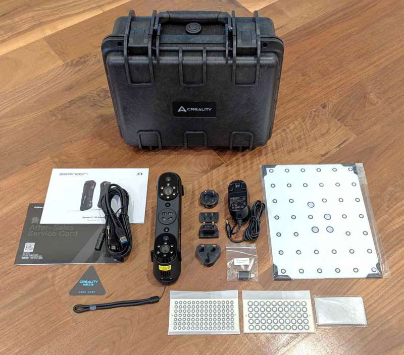
- Creality Sermoon S1 3D Scanner with lanyard
- Waterproof case
- USB 3.0 data cable (Type-C/Type-A)
- AC power adapter with four different country prongs
- Reflective markers (D6mm*10 sheets, D3mm*10 sheets)
- High-precision glass calibration plate
- Type-C adapter
- Cleaning cloth
- Quick start guide, certificate of conformity & warranty card
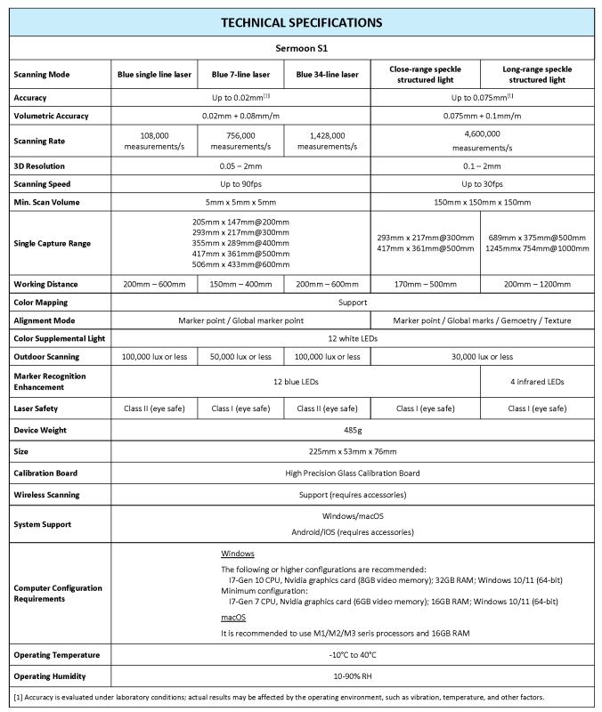
Tech specs
Design and features
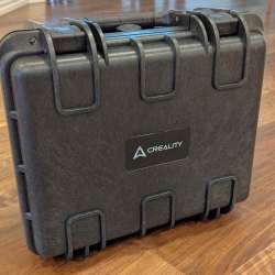
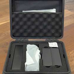
The Creality Sermoon S1 3D Scanner comes in a very nice, heavy-duty waterproof case. All the accessories come well-packed inside.
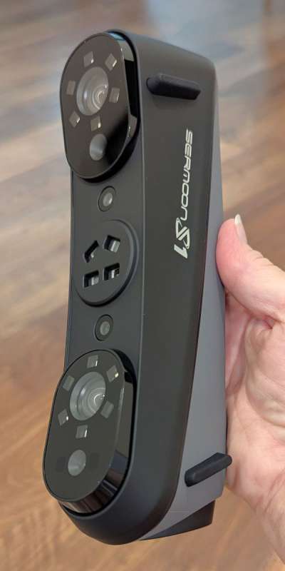
The S1 scanner can easily be held in your hand. It weighs 485 grams (~1 pound) and measures 225 mm L x 53mm W x 76 mm H. It looks and feels well-made. There are two raised rubber pads on each side of the scanner, so it remains stable when you place it on a surface when not using it. The grey area of the scanner is slightly textured to improve grip.
The scanner comes with a power adapter and different prongs for the country in which the user lives. The prongs slide into the adapter and snap in place.
Since I’ve never reviewed a 3D scanner before, I found some excellent YouTube videos from the channel “Tensile Creator” by Payo. His full review of the Sermoon S1 and his Beginner’s Guide were immensely helpful in understanding how the device and the software work and how the scanner compares to other Creality 3D scanners like the Raptor Pro. Apparently, both scanners come in the same type of case and are very similar in design.
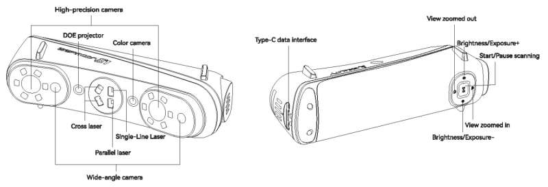
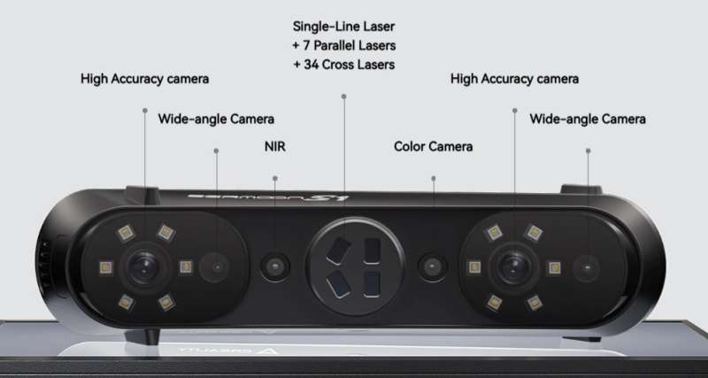
The S1 scanner has several cameras:
- High-accuracy cameras (2)
- Wide-angle cameras (2)
- Near infrared camera
- Color camera
It also has several lasers for scanning:
- Single laser line – scans small objects, deep pockets, or when you need scans with high precision and detail.
- 7 parallel laser lines – scans moderate-sized objects and captures small surface details up to 0.1 mm resolution.
- 34 cross laser lines – suitable for quick scanning; scans mid- to large-sized objects.
Scanning range:
The Sermoon S1 scanner website states that the scanning range is from 5 × 5 × 5 mm³ to as large as 4000 × 4000 × 4000 mm³.
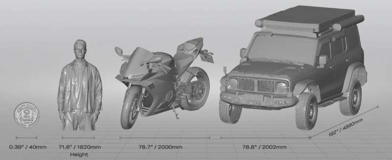
“With a hybrid system combining blue laser lines and infrared structured light, the Sermoon S1 supports a wide scanning range, from as small as 5 × 5 × 5 mm³ to as large as 4000 × 4000 × 4000 mm³. Ideal for automotive components, coins, bolts, figurines, or even the human body” (from the Creality website).
The bottom of the scanner has a USB-C port, as shown in the first photo above. On either side of the port are screw holes to help keep the USB-C cable connected to the scanner as you use it. The top and bottom of the scanner have vent holes to cool the electronics inside.
The scanner also has a control panel of buttons, as shown in the third screenshot above. There’s a Play/Pause button, Brightness/Exposure “+/-” buttons, and Zoom “+/” buttons.
Here are the buttons’ functions:
- Play/Pause button
-
- A short press of the Play/Pause button starts or pauses the scanning.
- A long press (2 seconds) of the button stops the scanning.
- Double-clicking the button switches between the three laser modes: single laser line, 7 parallel laser lines, or 34 cross laser lines.
-
- Brightness/exposure “+/-” buttons
-
- In Blue laser line mode, a short press of the button increases/decreases the brightness.
- In Infrared mode, these buttons increase/decrease the IR camera exposure.
-
- Zoom “+/-” buttons
-
- A short press of these buttons zooms in/out.
-
Assembly, Installation, Setup

Although I scanned all my objects while holding onto the scanner as shown above, there is a scanning bridge available (I don’t have the scanning bridge).
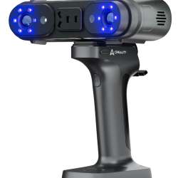
The Creality Scan Bridge (sold separately) attaches to the scanner via a quick-release mechanism (like those you would use on a camera for a tripod) and uses WiFi to wirelessly transmit the scan data to the software.
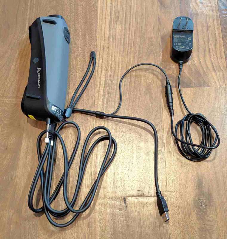
The Scan Bridge quick-release screw hole is located on the side of the scanner (it has a circular light grey cover in the black portion of the scanner, as shown in the photo above). Since I don’t have the Scan Bridge, I had to use the wired connection and stay close to my computer while scanning.
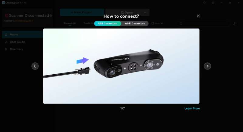
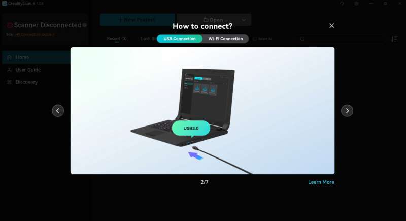
The photo above also shows how to connect the power and data cables to the scanner.
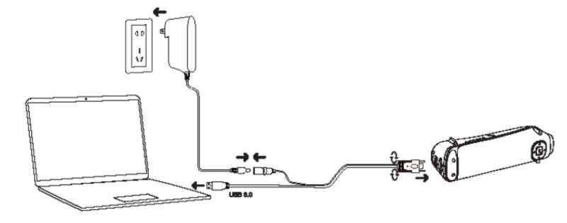
The above figure illustrates how to connect the scanner to power and your computer.
Creality Scan 4 software
One of the first things to do when using the Sermoon S1 3D scanner is to download and install the Creality Scan 4 software. The current version of the Creality Scan 4 software at the time of this writing is 1.2.8 for Windows.
Computer Requirements
The following are the computer requirements (or higher configurations) recommended to run the scanning software:
- Windows
-
- I7 Gen 10 CPU
- 32 GB RAM
- NVIDIA graphics card with 8GB video RAM
- Windows 10/11, 64-bit
-
- macOS
-
- Use M1/M2/M3 series processors and 16 GB RAM
-
After installing the software, it prompts you to connect the USB-C cable to the scanner and the computer. Don’t forget to plug the scanner into power. Yeah, I did that and even emailed Creality support about it. Right after I sent the email, I discovered my ID-10-T error and sent another email stating that they should disregard my previous email. Lol.
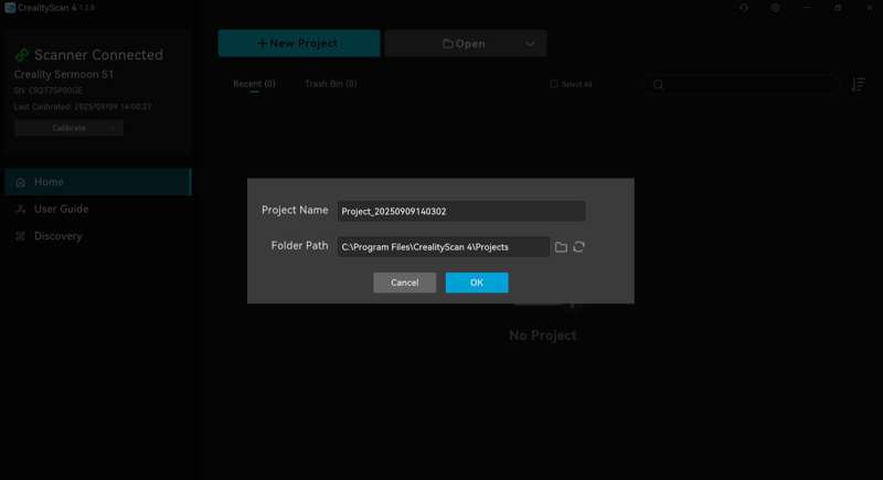
The software then provides you with a short Quick-Start guide about how to complete your first scan. Looks easy enough. But it’s a bit more involved than that. Just a bit.
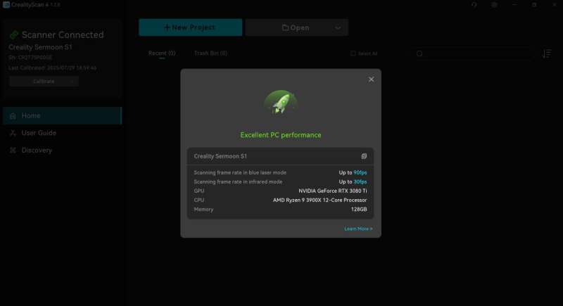
After showing me the Quick-Start steps to complete a scan, the software found that my computer had “Excellent PC performance” and reported my computer’s details:
- Scanning frame rate in blue laser mode: up to 90fps
- Scanning frame rate in infrared (IR) mode: up to 30fps
- GPU: NVIDIA GeForce RTX 3080 Ti
- CPU: AMD Ryzen 9 3900X 12-core processor
- Memory 128 GB
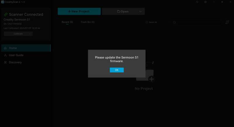
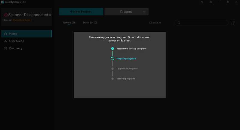
Then the software prompts you to update the scanner’s firmware.
There’s a mobile app you can use to scan, called Creality Scan, but you have to have a phone that can process the data. I have a Pixel 6 Pro and the app determined that my phone wasn’t up to par. It reported that there would be lag (center screenshot above). I tapped on the “Continue using” button to see if I might be able to test this.
I tried using the USB-A to USB-C adapter that comes with the scanner to plug it into my phone, but the app states that the “USB connection does not support scanning”. Well, that takes care of that.
Scanner calibration
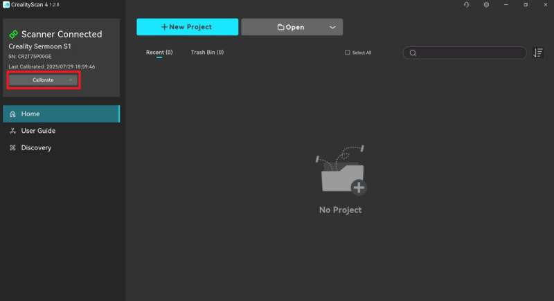
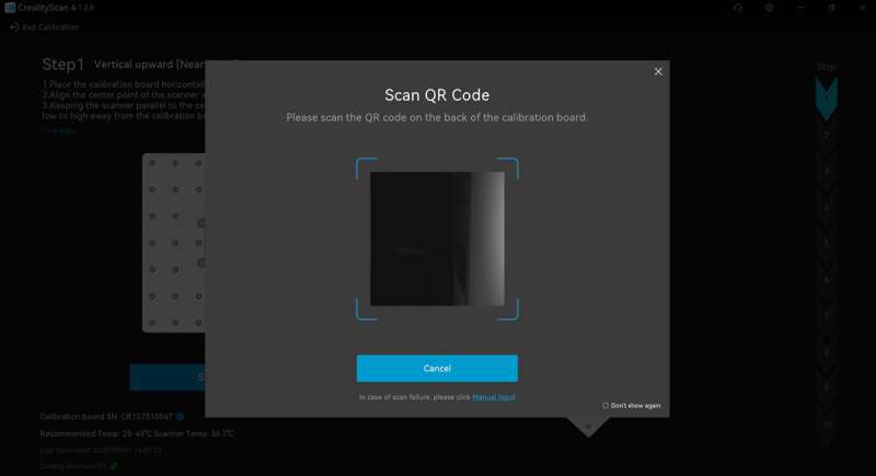
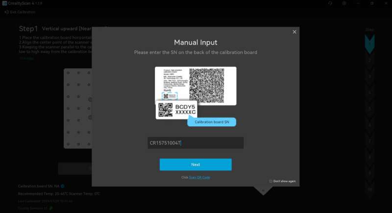
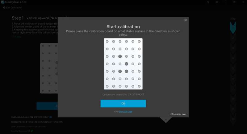
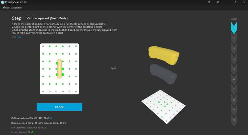
It is recommended that you calibrate the scanner before performing any scans. The Sermoon S1 comes with a glass board containing reflective markers. Be careful with this board and store it away in the case to avoid damaging or breaking it.
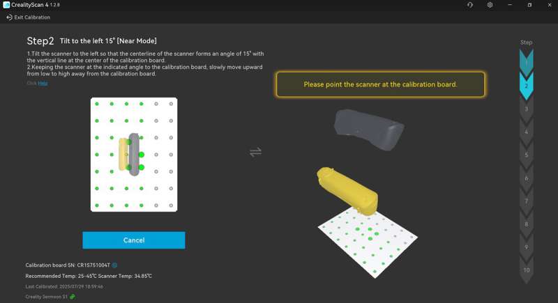
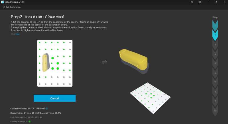
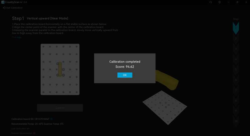
The Creality Scan 4 software steps you through the process to calibrate the scanner. I was prompted to hold the scanner directly above the calibration plate, tilt it to one side, then tilt it to another side, etc., and increase the elevation according to the images presented. When the calibration was complete, the software gave me a calibration score.
Performance
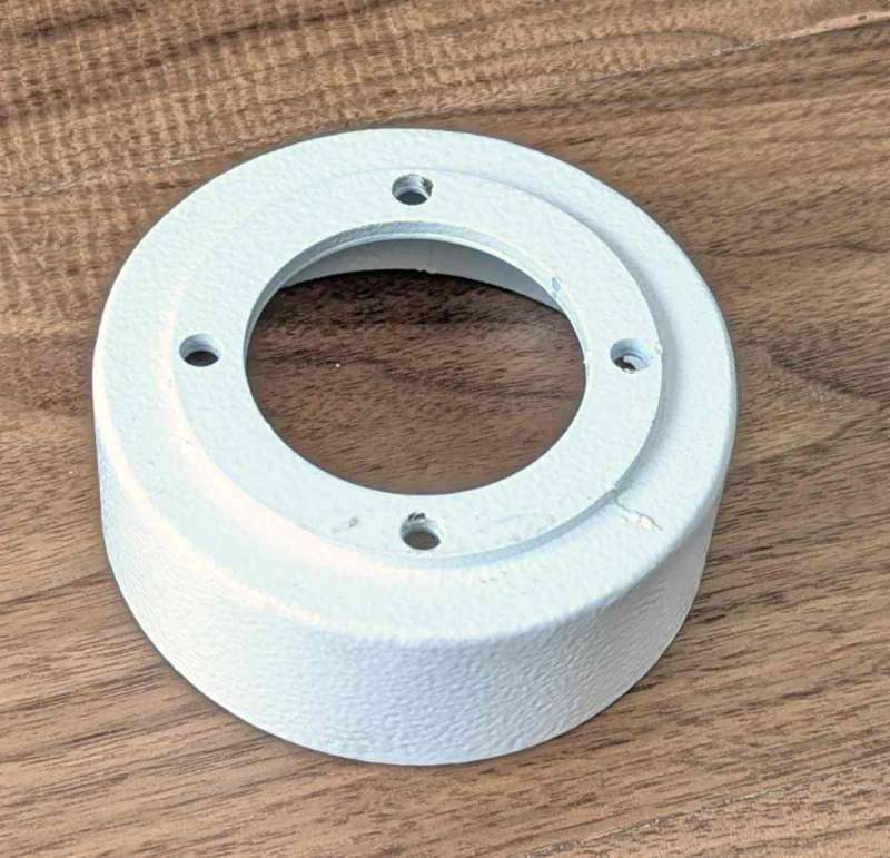
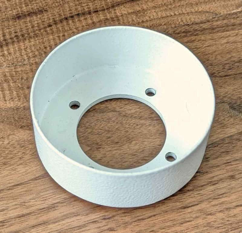
The above is one of the objects that I scanned. It’s a metal vent hose adapter.
Reflective markers and their placement
Reflective markers are used in many scanning situations to give the scanner reference points to ensure accurate scanning results (either on the object or on a base for the object). They are not always necessary.
Some objects have distinctive features that help the scanner maintain correct positioning and thus don’t need the markers, like scanning faces and bodies using infrared scanning.
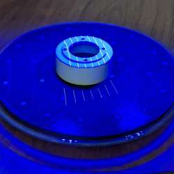
If there are very few distinctive features, markers are needed to scan the object. How far apart do they need to be? Well, I watched Payo’s videos and verified that the single-line laser can capture the markers when they are up to 10 cm apart max and the scanner is 21 cm away from the object. The 7 parallel laser-line mode and 34 cross laser-line mode are capable of capturing the markers when they are up to 21 cm apart max, and the scanner is 32 cm away from the object. These are the maximum distances. Payo mentions in one of his videos that the markers should be placed no more that 15 cm apart on large objects to increase scanning speed.
When markers are needed (and based on the aforementioned information), I decided to place the markers in random areas no more than about 15 cm apart on large objects, no more than 8 cm apart on medium-sized objects, and about 3-5 cm apart on small objects.
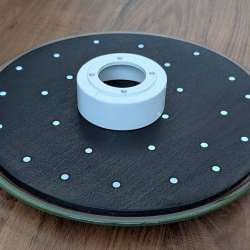
I used an old microwave turntable as my scanning platform/base. I cut a circular piece of plywood that fit on the glass plate to function as my base. I painted it black and then placed the reflective markers on the base in a random fashion, within about 5-8 cm of each other. I added more later to increase the speed and efficiency of the scan so that the markers were no more than 5 cm from each other.
- Note: markers are not needed on small objects. Instead, place markers on a turntable base to give the scanner reference points during a blue-line laser scan. You’ll have to perform multiple scans and combine them in the scanning software to create an entire digital 3D model.
- If you wish to hold the object while scanning, then you’ll most likely need markers on the object. When the object contains markers, you can potentially scan the entire thing in one scan instead of doing multiple scans and combining them later.
Blue Laser Mode scanning steps
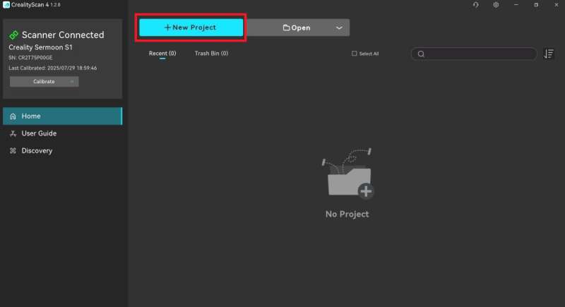
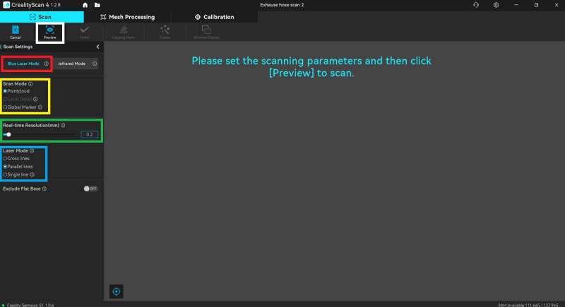
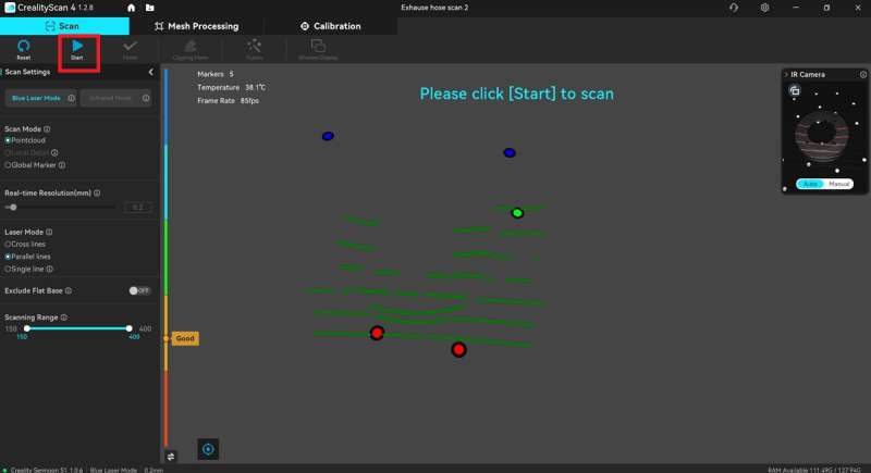
Since the documentation is scant when it comes to guiding the user on creating a complete digital 3D model, here are the steps that I’ve discovered will lead you to one, from start to finish. Click on images to view a larger size.
-
-
-
Pause the scan
Pause the scan by short-pressing the scanner’s “Play/Pause” button to view the results in the application. If you notice areas that you missed, continue scanning by short-pressing the “Play/Pause” button again.
-
Remove the base that the model sits on
-
-
Create a “Clipping plane”
After pausing the scan, click the “Clipping plane” button (in the yellow box in the center screenshot above) at the top of the application and use the Alt key + the left mouse button to select at least three markers (in small black boxes in the center screenshot above) to create the plane.
- Note: If the entire base is not selected (as shown in red), locate the green arrow that shows up in the center of the scan after you’ve selected three markers (arrow is shown in the white box in the center screenshot above). Click on that arrow and move it up or down to move the plane up or down to capture more of the base.
- Remove the base – Click on the checkmark button in the lower left of the screen (in the orange box in the center screenshot above) to remove the base.
-
-
-
Continue or Finish scanning
You can choose to continue scanning if you see gaps in the scan, or, in my case, I clicked on the “Finish” button at the top of the application.
-
-
-
-
-
Edit the scan
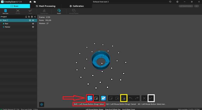
After finishing the scan, you can take this opportunity to remove any noise using the tools in the Edit toolbar for that scan (the bar shows up at the bottom of the scan layer view when the scan is finished, as shown by the red arrow in the screenshot above).
-
- Select area to edit – Use the lasso tool and the Shift key + the left mouse button (red boxes above) to select the desired area to edit (if you select an area you don’t want selected, use the Control key + the left mouse button to circle the area that needs to be unselected).
- Delete area – Next, click the “Delete” button in the Edit toolbar to delete the area (yellow box above).
- Save edits – And finally, click on the checkmark button to save your edits (white box above).
-
- Note: the Edit toolbar disappears after you save your edits. This appears to be a bug in the application. However, I discovered that after the meshing process, I could click on the view of the mesh and see the Edit toolbar there, and then immediately click on a view of a scan, and the Edit toolbar would show up there. So if you don’t see the Edit toolbar after your first edit of each scan, continue through to the meshing process and click on the mesh view, then a scan view. You’ll have to repeat this process for each of your scans in the project to do any additional editing. I illustrate this process in the video later on in the review.
-
-
-
Start a new scan if necessary
Once one scan is completed, you can start a new scan of a different area of the model to ensure you have a 360-degree capture of the object. This is often necessary when the model has no markers and is placed on a base that has markers.
-
- NOTE: Once placed on the base, you can’t move the model, or you risk making that particular scan unusable. If that happens, you can’t delete individual scans within a project, but you can add a new scan. When you’ve completed all your scans, you can select only the best scans to complete the project while ignoring the bad ones.
-
-
-
-
-
-
-
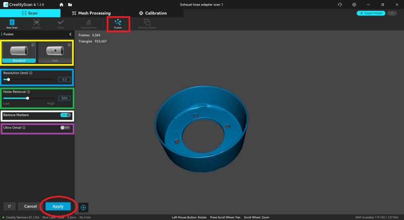
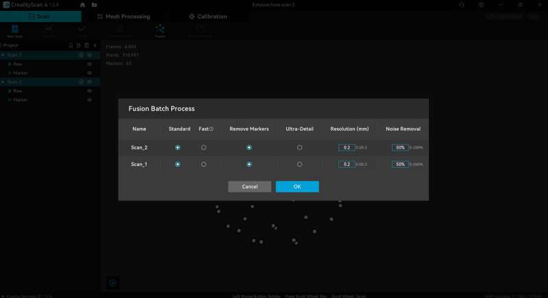
- Batch fusion – I completed two separate scans of the vent hose adapter and then performed the fusion for each at the same time (a.k.a., Fusion Batch Process). I selected the fusion settings as stated previously and clicked the “Ok” button to start the fusion process.
-
-
-
-
-
-
Aligning the scans before meshing
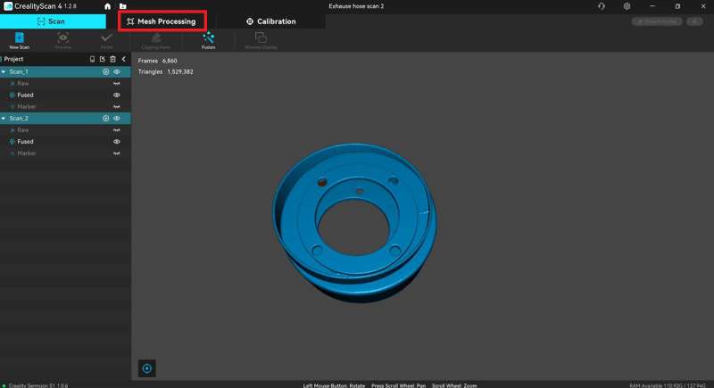
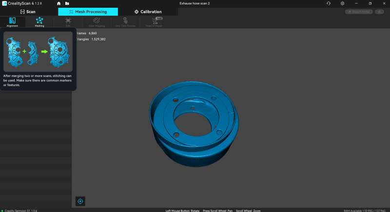
To align the scans together and make the object whole, click on the “Alignment” button, then select which scans you want to align. You can ignore poor scans and select the best ones. Try the “Auto” alignment first to see if it performs the alignment correctly, and if it doesn’t, you can then align them manually.
-
-
- Auto alignment of the scans – Most of the time, you can use the “Auto” alignment tool to correctly align the scans together by clicking on the “Auto” tab and clicking on the “Align” button.
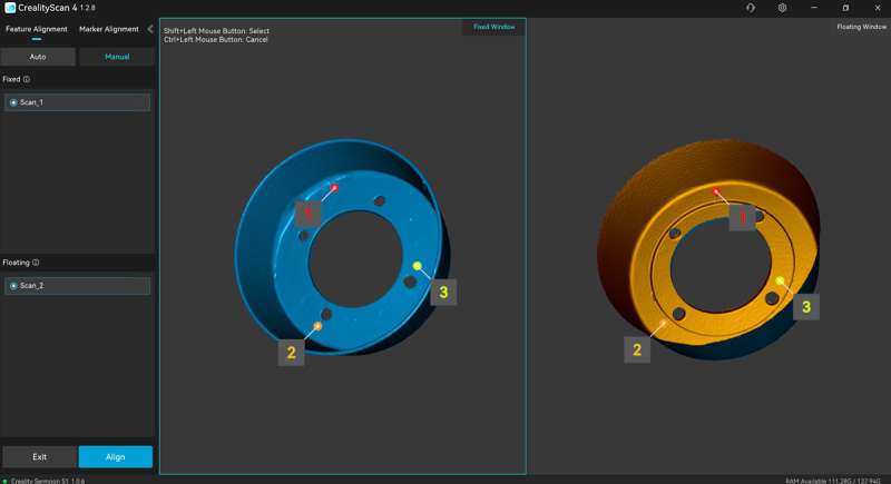
- Manual alignment of the scans – Since my scanned object was circular, I used the manual alignment (click the “Manual” tab) to ensure that it combined the scans correctly.
-
- Orient the scans – To manually align the scans, I looked for imperfections on the actual vent hose adapter and found them on the scans. I then oriented the scans in a way that made it easy for me to visualize how I wanted them merged.
-
-
-
-
-
-
-
-
-
-
- Select three points on each scan to align – I used the Shift key + left mouse button to select three points on each scan, such that point #1 on one scan aligned with point #1 on the other, and point #2 with point #2, and the same with point #3. The selection of these points doesn’t need to match exactly; they just need to be in the same general area on all scans.
- Align the scans – Click the “Align” button. Check the alignment and redo the manual alignment if necessary, then click the “Exit” button.
-
-
-
-
-
-
-
-
Mesh results and editing the results
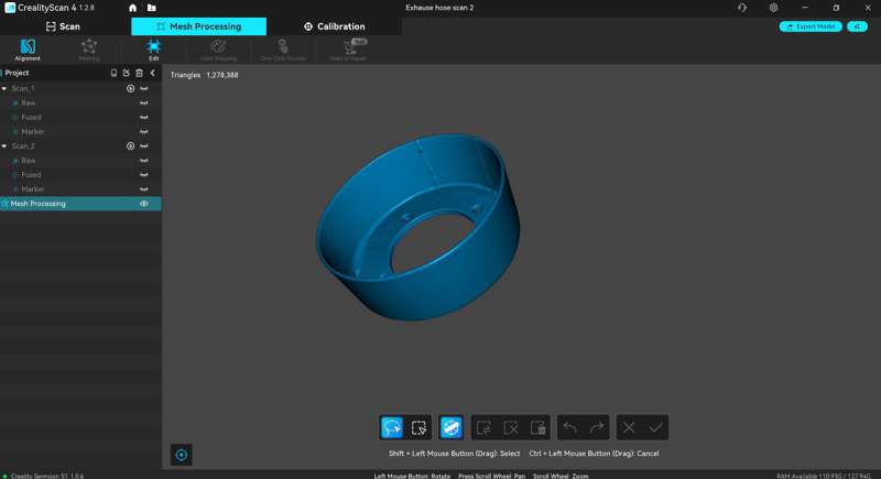
The results of the meshing process are shown above. I was impressed with the results. All of the imperfections on the actual vent hose adapter were captured in the final model. The only thing I noticed was that the scanned model wasn’t as smooth as the original. That may have to do with exposure/brightness settings. I noticed (after some practice) that some of my scans of other objects looked really rough, and after adjusting the exposure/brightness settings, things seemed to improve. I just need practice.
-
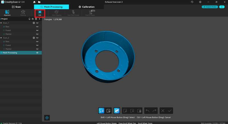
- Editing the mesh (if necessary) – If there are areas that need to be edited in the mesh results, you can use the tools in the Edit toolbar just like you do after scans are completed.
-
-
-
-
-
-
-
- Edit button – In addition to the Edit toolbar, there is an “Edit” button located at the top of the application (red box above) that allows you to do the following:…
-
-
-
-
-
-
-
-
-
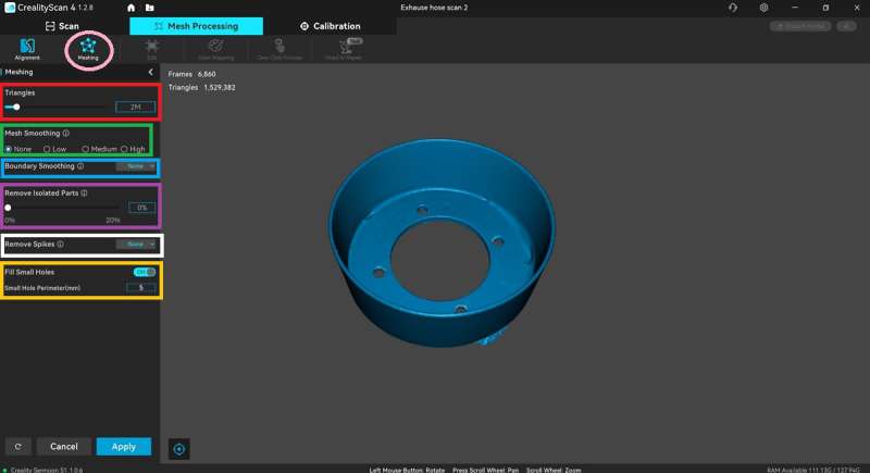
- Mesh simplification – Adjust the number of triangles and thus the amount of details (the higher the number of triangles, the more details).
- Mesh smooth –
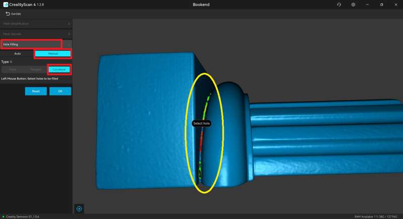
- Hole filling (red boxes above)
-
- Auto – I tried auto-filling the holes on different scans of multiple scanned objects, and it failed every time (application bug?), so I manually filled the holes.
- Manual – I selected “Curvature” for the type of holes I wanted filled (vs. “Plane” or “Tangent”). The holes were highlighted in green. When I hovered over them with my mouse, the area would turn red, and left-clicking on that area flagged the area to be filled. Once I selected all the areas I wanted filled in, I clicked the “Ok” button to fill the holes.
-
-
-
-
-
-
-
-
-
Export the meshed model
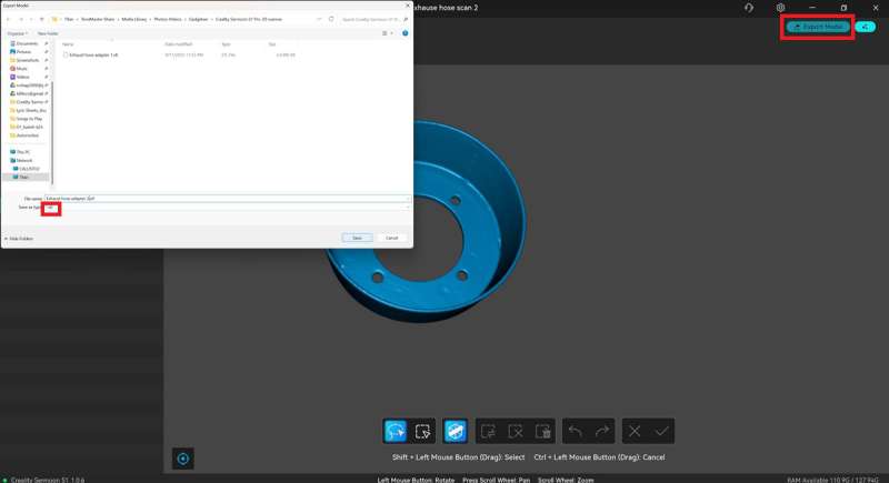
Click on the “Export model” button in the upper right corner of the application to export the model. You can export it as an STL, PLY, OBJ, or ASC file.
-
-
-
-
-
-
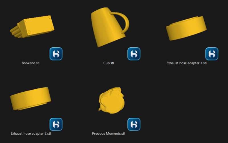
- After some practice, I was able to export several scans as STL files. That’s so awesome!
-
-
-
The trick to obtaining a good 3D model
The trick to obtaining a good 3D model is performing multiple scans of an object, editing those scans, fusing them (multiple times, if necessary), using the best ones to align together, then performing the mesh. If you notice imperfections in the mesh, you’ll edit the scans again, mesh them again, and even edit the mesh itself and fill in holes that were present in the scans. You can even delete poorly scanned spots from a raw scan and perform the fusion again. Then you use this new fused scan with another fused scan that has a good scan of the deleted area and align them, then perform the mesh again. You’ll go back and forth editing the scans, then meshing them again, and then editing the mesh itself before exporting the model. It’s a back-and-forth process that will eventually yield better results. That’s what worked for me. If you watch the 34-minute video provided later in this review, I think you will understand this process more clearly.
Other blue laser scan results
One of the most difficult scans for me was a TV stand foot. The top portion of the foot was smooth and not too difficult (except for the steep angle where the foot touched the base), but the underside was full of plastic cross braces that formed many deep pockets. Those were incredibly difficult to capture, even when using blue laser single-line scanning, as shown in the results above (last screenshot).
I tried placing markers on the part to see if it would improve the results, but it didn’t.
I tried scanning what I thought would be an easy object – a bookend. However, I quickly found that there are areas that are difficult to scan, even with the blue single-line laser. There were many holes to fill in the meshed model (yellow circle in the third screenshot above).
I tried scanning a full 88-key keyboard with blue line scanning. I placed markers on the keyboard about 15 cm apart. However, when I went to digitally remove the markers from the scanned results, there were ghosts of the markers all over the scanned image, as shown by the red arrows above. Also, upon closer inspection, the meshed scan looks rough in between the keys, even after scanning those areas using the single-line laser mode. Increasing the resolution may help with the rough areas.
One of the objects that I scanned using the 7 blue line laser mode and the single-line laser mode was a Precious Moments figurine. I performed four scans; I didn’t use the second one because overexposure revealed the laser striking lines, making the scan look rough instead of smooth. So, I took the rest of the scans, fused them, aligned them, and meshed them. The scans and meshes required multiple edits, including going back and forth between them and editing and meshing the scans multiple times to get it right, but it turned out nicely in the end.
Here’s a video of the scanning of the Precious Moment figurine from start to finish. It’s a 34-minute video; however, there are time stamps available in the YouTube video description. Click here to view it in YouTube to skip to different portions:
Infrared scanning
Infrared scanning can be a faster method for scanning large objects, especially if they have distinctive features. In this case, you can scan it without markers. However, when you perform the scan, you need to manipulate the scanner differently when compared to blue laser mode. You need to move the scanner in a very slow and steady manner.
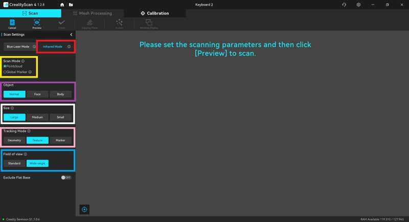
Infrared scan settings
Scanning using infrared, you need to select your desired settings:
- Scan mode: Pointcloud or Global Marker. Global Marker is “for mid-sized to large (≥250 x 250 x 250 mm³); it is recommended to scan Global Markers first and then pointclouds to achieve higher accuracy,” according to the Creality Scan 4 info icon.
- Object: Normal, Face, or Body.
- Size: Large, Medium, or Small (“Size” is not available when scanning a face or body).
-
- Large: 500 x 500 x 500 ~ 2000 x 2000 x 2000 mm³
- Medium: 250 x 250 x 250 ~ 500 x 500 x 500 mm³
- Small: 150 x 160 x 150 ~ 250 x 250 x 250 mm³
-
- Tracking mode: Geometry, Texture, or Marker; “Under Geometry mode, flat and regularly shaped objects may cause tracking loss while scanning. If the object lacks rich texture features, it is recommended to use Marker mode after randomly placing circular markers on the surface, according to the Creality Scan 4 info icon.
- Field of view (FOV): Standard or Wide-angle (FOV is only available for Large objects). “Standard FOV offers higher scanning accuracy, ideal for capturing fine details. Wide FOV covers a larger area, making it suitable for quickly scanning large objects or scenes,” according to the Creality Scan 4 info icon.
Infrared scan results
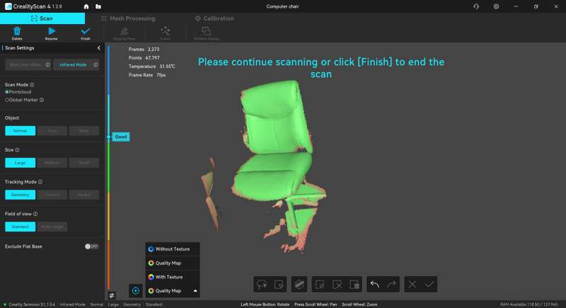
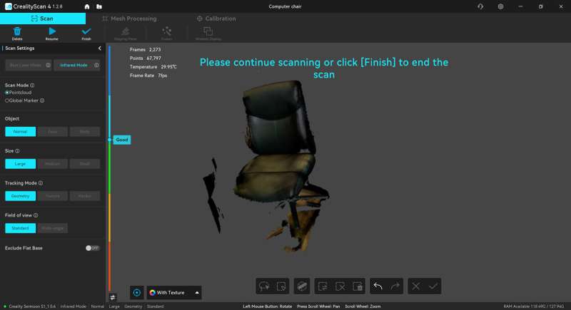
The above is a scan of our office chair.
Here are the settings I used for the chair:
- Scan mode: Pointcloud
- Object: Normal
- Size: Large
- Tracking mode: Geometry
- Field of View: Standard
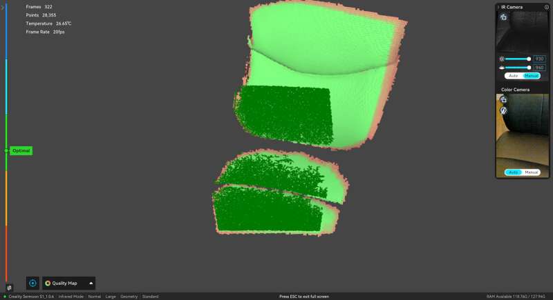
When scanning, you need to wait for the scan results to turn green. This lets you know that you have enough data for that area. If it’s not green, you need to keep scanning.
When you view the scan results, you can select which type of view you prefer, as shown in the #3 screenshot above. There is the “Quality Map,” which is the default setting, then there’s the “Without Texture” and “With Texture”. “With Texture” is essentially photos stitched over the scan. It’s pretty cool!
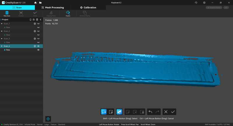
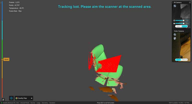
One thing I noticed was that if you go too fast while scanning without markers (I scanned our keyboard again without markers), the object can shift, the scanner loses track of it and starts scanning in a different place, and then the scan becomes unusable. Notice how the whole keyboard shows up twice in the above screenshot. I need lots more practice with infrared scanning.
Final thoughts
The Creality Sermoon S1 3D Scanner is a good tool to have to replicate an object or part and avoid having to reverse engineer it. What struck me most as a first-time user was how much practice it takes to obtain decent scans. Scanning an object requires you to watch the software view to ensure you’ve gotten the entire surface, while at the same time, watching the scan distance meter to ensure you are at the optimal distance from the object. Making sure you have the correct exposure and brightness settings also helps reduce the laser striking lines in the scan that can make the scan look rough instead of smooth.
Most of the issues I had were a matter of getting more experience with the scanner. I noticed that there are a handful of things that need some attention: documentation could be improved to help the user better understand how to create an entire 3D model from start to finish (including all the back-and-forth edits of scans, fusing multiple times, meshing multiple times, editing some more, and meshing again to get the final product). Also, the Edit toolbar for each scan disappears, digitally removing the markers from the scan leaves behind a ghost of the marker; you can’t delete individual scans within a project, and auto-filling holes never worked for me. So it would seem that the software needs some updating.
Even though the scanner is expensive, I think many makers would appreciate having the Creality Sermoon S1 Scanner to create digital 3D versions of objects instead of having to reverse engineer them. I know I appreciate it.
What I like about the Creality Sermoon S1 3D Scanner
- Turning an object into an STL, PLY, OBJ, or ASC file is incredibly useful.
- Saves time from reverse engineering.
- After some practice, my scans turn out nicely.
- The waterproof case is wonderful.
What needs to be improved?
- Provide better documentation, especially when editing the scans to clean them up to make a useful digital 3D model.
- The Edit toolbar in the Creality Scan 4 version 1.2.8 disappears in the scans.
- You can’t delete individual scans without deleting the entire project’s scans.
- Auto-filling holes never worked for me.
- Removing markers from scans often leaves ghosts of the markers on the scan.
- Include the scanning bridge.
- It’s expensive.
Price: $2699.00
Where to buy: Amazon
Source: The sample of this product was provided for free by Creality. Creality did not have a final say on the review and did not preview the review before it was published.
Check out these other 3D scanner reviews!
Love our content?
Sign up for our newsletter today.
No ads, no spam, just links to our latest articles!


